Longitudinal & Transverse Waves
Every wave belongs to one of two families, sorted purely by the direction its oscillation points relative to the direction the wave is travelling. That single geometric distinction turns out to explain why light can be polarised and sound can't — and why that fact is one of the clearest pieces of evidence physicists have for how light actually behaves.
Two families of wave
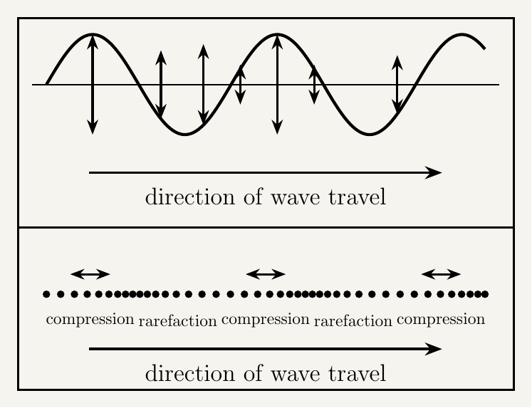
In a transverse wave, the particles of the medium (or the oscillating field) oscillate perpendicular to the direction the wave travels. A wave sent along a rope by shaking one end up and down is transverse. All electromagnetic waves — radio, microwaves, infrared, visible light, ultraviolet, X-rays and gamma rays — are transverse, with the oscillating electric and magnetic fields perpendicular to the direction of travel (and to each other).
In a longitudinal wave, the particles oscillate parallel to the direction of travel. Sound is the standard example: air molecules are pushed back and forth along the same line the sound travels, creating alternating regions of compression (bunched closer, higher pressure) and rarefaction (spread further, lower pressure).
In a vacuum, every electromagnetic wave — regardless of frequency or wavelength — travels at the same speed, $c \approx 3.00\times10^{8}\,\text{m}\,\text{s}^{-1}$. Radio waves and gamma rays differ enormously in frequency and wavelength, but not in vacuum speed; the wave equation $c=f\lambda$ still has to balance, so a higher frequency simply means a proportionally shorter wavelength.
The electromagnetic spectrum
All electromagnetic waves are the same kind of thing — an oscillating electric and magnetic field, travelling at $c$ in a vacuum — differing only in frequency and wavelength, related by $c=f\lambda$. The continuous range of frequencies is divided by convention into seven named regions, from lowest frequency (longest wavelength) to highest (shortest):
| Region | Approx. wavelength range | Typical use |
|---|---|---|
| Radio | > 1 mm (up to km) | Broadcasting (radio, TV signals) |
| Microwave | 1 mm – 30 cm | Satellite communications, cooking |
| Infrared | 700 nm – 1 mm | Thermal imaging, remote controls |
| Visible | 400 nm – 700 nm | Human vision |
| Ultraviolet | 10 nm – 400 nm | Sterilisation |
| X-ray | 10 pm – 10 nm | Medical imaging |
| Gamma | < 10 pm | Cancer treatment, sterilisation |
Because $c$ is fixed, ordering by increasing frequency is the same as ordering by decreasing wavelength — radio waves have the longest wavelengths and lowest frequencies, gamma rays the shortest wavelengths and highest frequencies. The boundaries between neighbouring regions aren't sharp physical cutoffs, just conventional dividing lines that vary slightly between sources.
Polarisation: evidence for transverse waves
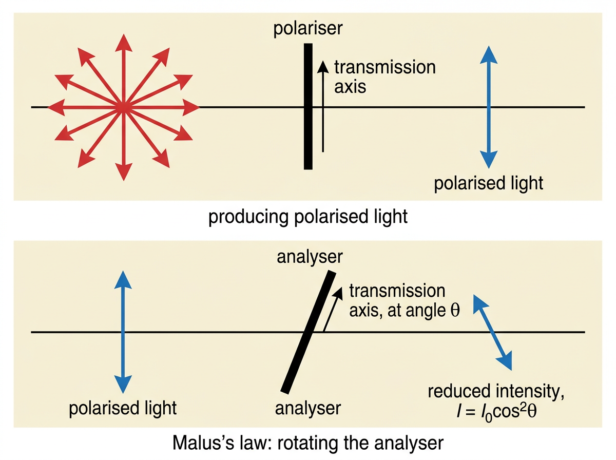
An unpolarised transverse wave, like light from an ordinary bulb, oscillates in every direction perpendicular to its direction of travel simultaneously. Polarisation restricts the oscillation to a single plane containing the direction of travel, filtering out every direction except one.
A polarising filter only allows through oscillations aligned with its own transmission axis. For a transverse wave, that's coherent, since the oscillation direction is perpendicular to the direction of travel, leaving an entire plane of directions to restrict.
For a longitudinal wave, this doesn't work: its oscillation is locked onto the single line along which the wave travels — there's no perpendicular plane of directions to restrict, since particles only move backward and forward along that one line. A polarising filter placed in a sound wave's path has nothing to act on.
That's why the ability to be polarised is evidence that a wave is transverse: only a transverse wave has more than one possible oscillation direction to restrict. That light can be polarised — readily demonstrated by looking through two polarising filters and rotating one — confirms directly that light is a transverse wave.
Malus's law: the transmitted intensity through a rotated polariser
Once light has passed through one polarising filter, it's polarised in a single, definite plane. If that polarised light then meets a second polarising filter — usually called the analyser — set with its transmission axis at some angle $\theta$ to the light's plane of polarisation, only part of the light gets through, and exactly how much depends on $\theta$. This relationship is called Malus's law.
The core requirement is the qualitative argument above — that polarisation is possible for transverse waves and impossible for longitudinal ones. Malus's law, derived below, extends this to a precise, quantitative relationship: know $I=I_0\cos^2\theta$, and be able to use it to find a transmitted intensity or required rotation angle.
Applications of polarisers
Polaroid material is a widely used polarising filter, made from long-chain molecules aligned in one direction that absorb light oscillating parallel to the chains while transmitting light oscillating perpendicular to them. It's used in sunglasses to cut glare — light reflected off water or a road becomes partially polarised in the horizontal plane, so Polaroid sunglasses with a vertical transmission axis block much of that glare. It's also used in LCD screens and photography filters.
Polarisation also matters for radio and television signal transmission. A transmitting aerial launches radio waves polarised in the same plane as the aerial itself. A receiving aerial only picks up the component aligned with its own length, so the aerials have to be aligned for efficient signal transfer — one mounted at right angles to the transmitter would pick up almost nothing. That's why domestic TV aerials are mounted with a specific, deliberate orientation relative to the local transmitter.
Key takeaways
- Transverse waves oscillate perpendicular to the direction of energy transfer (e.g. electromagnetic waves, waves on a string); longitudinal waves oscillate parallel to it (e.g. sound), producing compressions and rarefactions.
- All electromagnetic waves travel at the same speed in a vacuum, $c \approx 3.00\times10^8\,\text{m}\,\text{s}^{-1}$, regardless of frequency or wavelength.
- The electromagnetic spectrum, in order of increasing frequency (decreasing wavelength): radio, microwave, infrared, visible, ultraviolet, X-ray, gamma — each with distinct practical uses, from broadcasting to medical imaging.
- Polarisation restricts oscillation to a single plane — possible for transverse waves because they have a perpendicular plane of oscillation directions to restrict, impossible for longitudinal waves because their oscillation is locked to a single line.
- The fact that light can be polarised is direct evidence that light is a transverse wave.
- Malus's law, $I = I_0\cos^2\theta$, gives the intensity transmitted through an analyser set at angle $\theta$ to the light's plane of polarisation — full transmission at $\theta=0°$, zero at $\theta=90°$ (crossed polarisers).
- Polaroid material polarises light by absorbing one oscillation direction; it's used to cut glare in sunglasses and manage reflections in photography and displays.
- Transmitting and receiving aerials must be aligned in the same plane of polarisation for efficient signal reception — misaligned aerials receive very little signal.