Electromagnetic Induction & Faraday's Law
Move a magnet near a coil of wire and, with no battery in sight, a voltage appears across the coil's ends. This is electromagnetic induction, the principle behind every generator and transformer on the electrical grid, and it comes down to one deceptively simple idea: a changing magnetic environment always induces an emf.
Magnetic flux
Before induction can be described precisely, it helps to have a quantity for "how much magnetic field passes through a given area." That quantity is magnetic flux, $\Phi$:
where $B$ is magnetic flux density and $A$ is the area of the surface, measured with the field perpendicular to that area (at an angle, only the perpendicular component of $B$ contributes, giving $\Phi=BA\cos\theta$). Flux is measured in webers (Wb), where $1\,\text{Wb}=1\,\text{T m}^2$.
For a coil of $N$ turns, the more useful quantity is flux linkage, $N\Phi$ — treating the coil as though the same flux threads through each of its $N$ turns, so total linkage scales directly with the number of turns.
Faraday's law
The central result of electromagnetic induction is that an emf is induced in a circuit whenever the magnetic flux linkage through it is changing — whether from a magnet moving relative to a stationary coil, a coil moving relative to a stationary magnet, or a nearby circuit's current changing over time. Faraday's law: induced emf is directly proportional to the rate of change of flux linkage.
A faster rate of change — a magnet plunged quickly through a coil, or a coil with many turns — produces a correspondingly larger induced emf. If flux is changing at a constant rate, $\dfrac{d\Phi}{dt}$ can be read as $\dfrac{\Delta\Phi}{\Delta t}$; if the rate is itself varying, the gradient of a flux-linkage-against-time graph gives the emf at that instant.
Lenz's law and the meaning of the minus sign
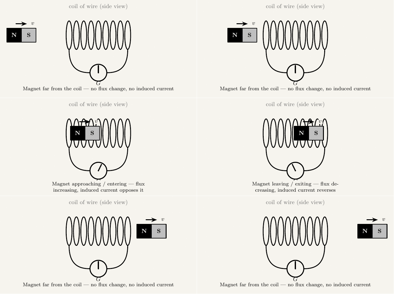
The negative sign in Faraday's law encodes a separate physical statement, Lenz's law: the direction of an induced emf (and any resulting current) always opposes the change in flux that produced it.
Lenz's law is a direct requirement of energy conservation. If an induced current instead assisted the change that created it, the flux change would accelerate uncontrollably and the system would generate energy from nothing. Because the induced current always opposes the change, external work always has to be done to push a magnet into a coil or keep a generator turning against the induced current's magnetic drag — and that external work is precisely what becomes the delivered electrical energy.
Practically, Lenz's law lets you work out the direction of an induced current: a magnet's north pole approaching a coil induces a current whose field opposes the approaching pole — the coil's near face effectively becomes a north pole, repelling the magnet. Withdraw the magnet instead, and the induced current reverses to try to attract it back, again opposing the change rather than the motion specifically.
Required Practical: Magnetic Flux Linkage
This is AQA's Required Practical 11: investigating electromagnetic induction.
Equipment
| Equipment | Purpose |
|---|---|
| Search coil (known turns, area) | Detects the induced emf produced by the changing flux |
| Solenoid or Helmholtz coils + signal generator | Produces a known, continuously changing (alternating) magnetic field |
| Oscilloscope or data logger with a voltage sensor | Measures the induced emf, avoiding the difficulty of timing a single fast-moving event by hand |
| Clamp/mount for the search coil | Holds the coil at a fixed, reproducible position and orientation |
Method
Sources of error and how to minimise them
If the coil's position or orientation relative to the field source shifts between readings, the flux linkage changes for reasons unrelated to the variable being tested. Use a fixed clamp or mount to keep the geometry constant throughout.
Mains leads and other live equipment nearby can induce a small additional emf unrelated to the field under test. Keep the setup well away from other electrical equipment and mains cabling.
An oscilloscope or data logger may display peak, peak-to-peak, or rms voltage depending on its settings. Be consistent about which value is being read and used throughout the analysis.
The frequency and amplitude of the current driving the field must stay genuinely constant across repeated readings — any drift changes the flux's rate of change independently of the variable actually being tested. Check the signal generator's display before each reading.
Key takeaways
- Magnetic flux $\Phi=BA$ (webers, Wb); flux linkage for a coil of $N$ turns is $N\Phi$.
- Faraday's law: $\varepsilon=-N\dfrac{d\Phi}{dt}$ — induced emf is proportional to the rate of change of flux linkage.
- Lenz's law (the minus sign): the induced emf always opposes the change producing it — a direct consequence of conservation of energy, not a separate assumption.
- (AQA Required Practical 11) Faraday's law is tested by measuring induced emf in a search coil as flux linkage is varied (via turns, area, or rate of change) using an alternating field, confirming a directly proportional relationship.