Alternators
Electromagnetic induction told us that a changing flux drives an emf. An alternator turns that idea into a machine: spin a coil inside a magnetic field, and the flux through it changes continuously, generating a smooth alternating emf. This lesson starts from the simplest possible case of motional emf — a rod sliding through a field — before deriving the alternator's emf from first principles and looking at how it gets that emf out to an external circuit.
The simplest case: a straight conductor moving through a field
Before considering a rotating coil, it's worth seeing the simplest possible example of motional emf: a straight conducting rod of length $L$, sliding at constant velocity $v$ along two parallel rails, through a uniform magnetic field $B$ perpendicular to the plane the rod sweeps out. The rails and rod together form a complete circuit, so any emf induced in the rod can drive a current around it.
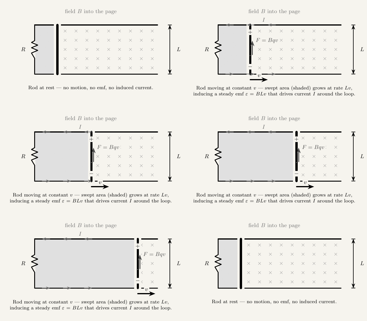
The same result falls straight out of the force on the rod's own charge carriers, without mentioning flux at all. Moving with the rod at velocity $v$, each free charge $q$ inside it feels a magnetic force $F=Bqv$ (the same expression derived in the previous lesson), pushing positive charge toward one end of the rod and leaving the other end negative. Charge keeps separating until the resulting electric field inside the rod is strong enough to balance the magnetic force:
and since the potential difference across a uniform field over a length $L$ is $V=EL$, this gives $V=BvL$ — identical to the emf found from the flux argument. Changing flux and force on moving charges are two views of exactly the same physics.
An alternator's rotating coil relies on exactly this effect, applied to the two sides of the coil that cut through the field as it turns — each side behaves like a short "rod" moving through $B$, and summing the motional emf around the whole loop, turn after turn, is exactly what leads to $\varepsilon=BAN\omega\sin(\omega t)$ below.
How an alternator generates emf
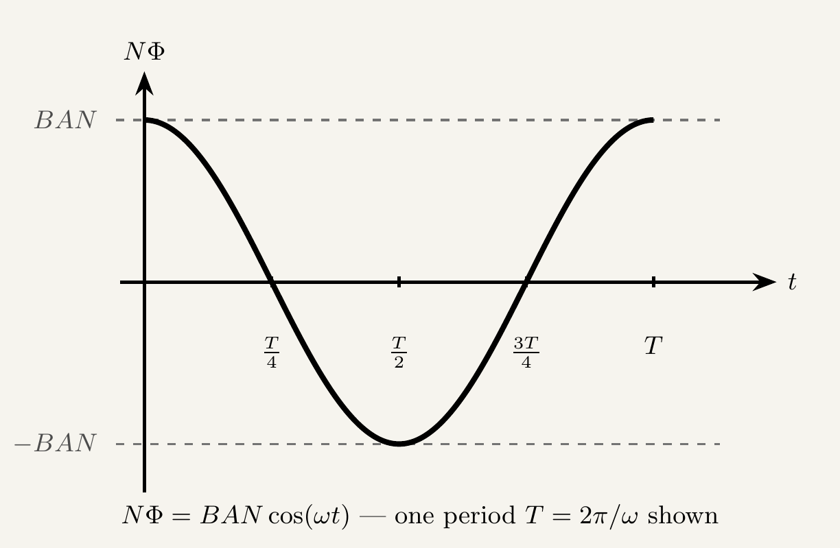
An alternator is a coil of $N$ turns, area $A$, rotating at constant angular velocity $\omega$ inside a uniform magnetic field of flux density $B$. As the coil turns, the angle $\theta$ between the field and the normal to the coil changes continuously, so the flux linkage through the coil changes continuously too:
Faraday's law says the induced emf is the negative rate of change of flux linkage, $\varepsilon = -N\dfrac{d\Phi}{dt}$. Differentiating $\Phi=BA\cos(\omega t)$ with respect to time:
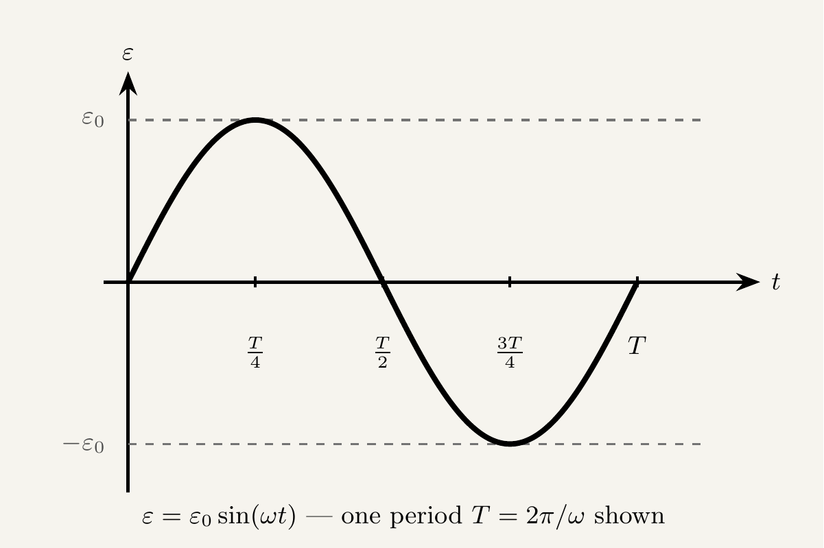
The peak emf is $\varepsilon_0 = BAN\omega$, reached when $\sin(\omega t)=1$. So the full expression is often written $\varepsilon=\varepsilon_0\sin(\omega t)$ — a smooth, continuously alternating sine wave, one full cycle per rotation of the coil.
Peak emf happens where you might not expect
It's tempting to think the emf is largest when the flux through the coil is largest, but it's the opposite. Flux linkage $N\Phi=BAN\cos(\omega t)$ peaks when the coil's plane is perpendicular to the field — at that instant the coil is momentarily turning "along" the field lines, so flux is barely changing, and the emf ($\propto$ rate of change of flux) is near zero. The emf peaks instead when the coil's plane is parallel to the field, flux itself is zero, but the coil is sweeping through field lines as fast as it can — the rate of change of flux is at its maximum.
Slip rings vs split-ring commutators
How the rotating coil connects to an external circuit determines what kind of output you get. An alternator uses two slip rings — continuous conducting rings, one fixed to each end of the coil, each permanently in contact with its own carbon brush. Because each slip ring always touches the same end of the coil, the external circuit sees the coil's true output: a smooth, continuously alternating emf, exactly as derived above.
A DC generator (or motor run in reverse) instead uses a split-ring commutator — a single ring cut into two halves, each half connected to one end of the coil. Every half-turn, the brushes swap which half of the coil they're touching, which flips the connection at exactly the moment the coil's own emf would have flipped sign. The result is a rectified, always-positive output that pulses between zero and $\varepsilon_0$ rather than alternating — the mechanical equivalent of a full-wave rectifier.
Key takeaways
- A straight rod of length $L$ moving at velocity $v$ through a field $B$ has a motional emf $\varepsilon=BLv$ — derivable either from the rate of change of flux swept out, or from the force $F=Bqv$ on the rod's own charge carriers.
- A coil of $N$ turns and area $A$, rotating at angular velocity $\omega$ in a field $B$, has flux linkage $N\Phi=NBA\cos(\omega t)$.
- Applying Faraday's law gives the induced emf: $\varepsilon=BAN\omega\sin(\omega t)=\varepsilon_0\sin(\omega t)$, with peak emf $\varepsilon_0=BAN\omega$.
- Emf and flux are 90° out of phase: emf peaks when flux is zero (coil plane parallel to the field, sweeping through field lines fastest), and is zero when flux peaks (coil plane perpendicular to the field, momentarily not cutting field lines).
- Slip rings keep the same end of the coil connected to the same brush at all times, so an alternator outputs a smooth alternating emf.
- A split-ring commutator swaps connections every half-turn, rectifying the output into a one-directional, pulsing emf — this is how a DC generator differs from an alternator.