Discharging Capacitors
Let a charged capacitor discharge through a resistor and the current doesn't switch off cleanly — it dies away smoothly, fast at first and ever more slowly, never quite reaching zero. That shape, exponential decay, turns up everywhere in physics, and the capacitor-resistor circuit is the cleanest place to meet it properly.
Discharging through a resistor
Connect a charged capacitor across a resistor and charge flows off the plates, driven by the potential difference across them. As charge $Q$ falls, the potential difference $V=Q/C$ falls too, reducing the discharge current $I=V/R$ — so the rate of discharge continuously slows. This self-limiting behaviour produces an exponential decay rather than a straight-line fall to zero.
The time constant
The quantity $RC$ in the exponent has units of time (ohms times farads gives seconds) and is called the time constant, $\tau=RC$. It sets the timescale of the discharge — a larger resistance or capacitance means a slower discharge, since either limits how quickly charge can flow.
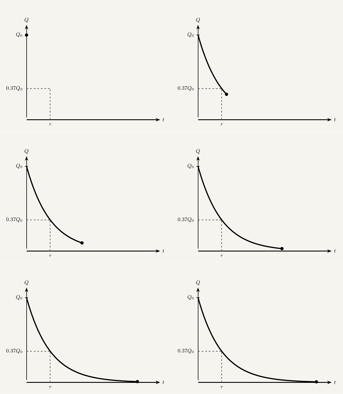
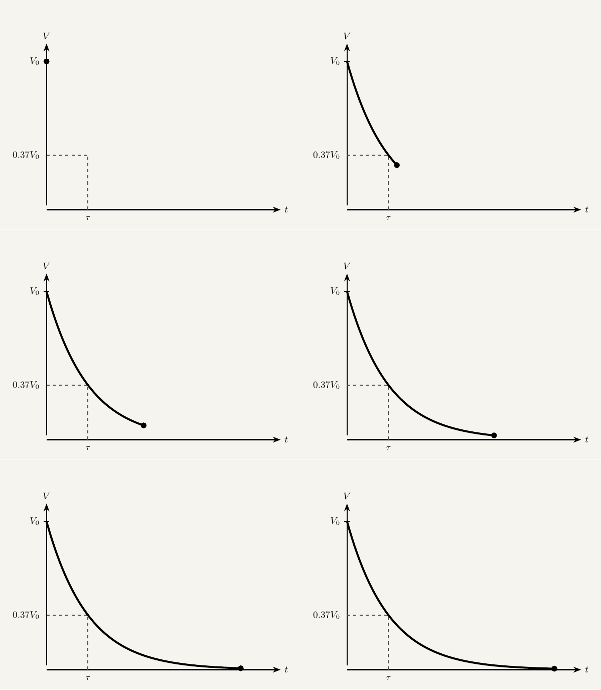
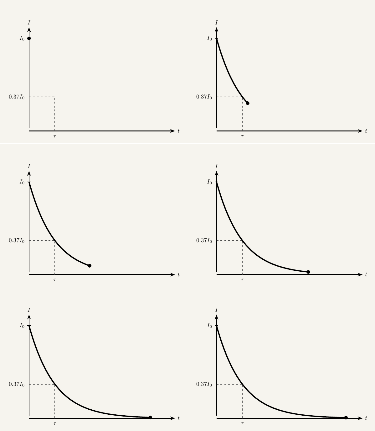
Substituting $t=\tau=RC$ into $V=V_0e^{-t/RC}$ gives $V=V_0e^{-1}\approx0.37V_0$. So after one time constant, the potential difference (and charge, and current) has fallen to about 37% of its initial value — a 63% drop. This holds regardless of starting voltage: after a further time constant, whatever value $V$ has reached falls to 37% of that value, and so on. Since the decay never mathematically reaches zero, a capacitor is usually considered practically discharged after about five time constants, by which point under 1% of the original charge remains.
All three quantities — charge, potential difference and current — trace out the identical decay shape, just rescaled. Each graph below is marked at one time constant $\tau=RC$, where the quantity has fallen to about 37% of its starting value.
Required Practical: Discharging a Capacitor
This is AQA's Required Practical 9: investigating capacitor charge/discharge.
Equipment
| Equipment | Purpose |
|---|---|
| Capacitor (known/measurable capacitance) | The component being charged and discharged |
| Resistor (known resistance) | Sets the time constant $\tau=RC$ together with the capacitor |
| Power supply | Charges the capacitor fully before discharge begins |
| Switch (or two-way switch) | Switches between charging and discharging the capacitor |
| Voltmeter, or data logger with a voltage sensor | Records voltage across the capacitor over time; a data logger removes manual reaction-time error |
| Stopwatch (if not using a data logger) | Times the readings at regular intervals |
Method
Sources of error and how to minimise them
Reading a stopwatch and voltmeter by hand introduces reaction-time and timing-mismatch error, especially early in the discharge when the voltage is changing fastest. Use a data logger for continuous, precisely time-stamped recording wherever available.
A real capacitor is never a perfect insulator between its plates — a small leakage current flows internally even with no external circuit connected, so the capacitor loses charge that never appears in the resistor's current or the voltmeter's reading. Use a high-quality capacitor and a voltmeter/data-logger input with very high resistance to minimise this effect.
If discharge begins before the capacitor has reached the full supply voltage, $V_0$ in the analysis is wrong. Wait for the voltmeter reading to stabilise fully before switching to discharge and starting the timer.
Key takeaways
- Discharge: $Q=Q_0e^{-t/RC}$, $V=V_0e^{-t/RC}$, $I=I_0e^{-t/RC}$ — all three decay with the same exponential shape and time constant.
- The time constant $\tau=RC$ (units of seconds) is the time for the discharging quantity to fall to about 37% (i.e. by 63%) of its value at the start of that interval; a capacitor is practically discharged after about five time constants.
- (AQA Required Practical 9) The time constant is found experimentally by discharging a capacitor through a known resistor and recording $V$ (or $I$) against $t$; plotting $\ln V$ against $t$ linearises the decay, giving a straight line of gradient $-1/RC$.
- Sources of error include leakage current through the capacitor's imperfect insulation, and reaction-time error on manually timed readings, best avoided using a datalogger.