Dielectrics
Slide an insulating material between the plates of a capacitor and, without touching the charge on either plate, its capacitance goes up. This lesson looks at why — and turns that "why" into the parallel plate capacitor formula, $C=\dfrac{\varepsilon_0\varepsilon_r A}{d}$.
What is a dielectric?
A dielectric is an electrically insulating material — it doesn't conduct, so no charge can flow through it. Slid between the plates of a capacitor, filling the gap, a dielectric increases the capacitance well beyond what the same plates would achieve with only a vacuum (or air, which behaves almost identically to a vacuum) between them. This is the standard way real capacitors pack useful capacitance into a small physical size: waxed paper, ceramic, mica and various plastics all serve as dielectrics in commercial capacitors.
Why a dielectric increases capacitance
A dielectric is built from molecules that are polar (or become polarised by an external field) — each one has a slightly positive end and a slightly negative end. Left alone, these molecules point in random directions and cancel out. But placed in the electric field between charged capacitor plates, they twist to align with it: the negative end of each molecule turns toward the positive plate, and the positive end toward the negative plate.
This alignment is called polarisation. Across the bulk of the dielectric the aligned molecules still cancel out, but at its two faces they don't: a layer of negative bound charge appears on the face nearest the positive plate, and a layer of positive bound charge on the face nearest the negative plate. This induced surface charge creates its own electric field, pointing opposite to the field from the plates — so the net field inside the dielectric is weaker than it would be with a vacuum gap.
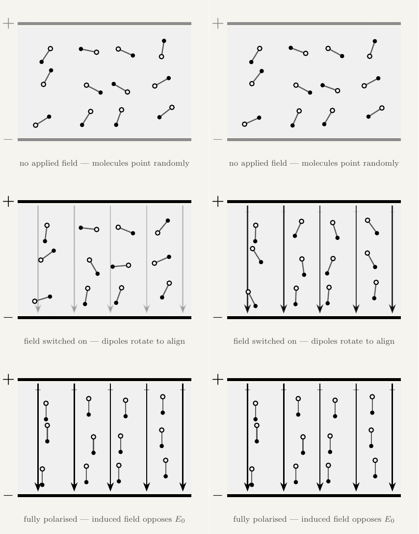
That induced field points against the field from the plates, so the two partially cancel: the net field between the plates — and with it the potential difference $V=Ed$ — falls, even though the charge $Q$ on the plates hasn't changed. Since $C=Q/V$, a smaller $V$ for the same $Q$ means a larger $C$.
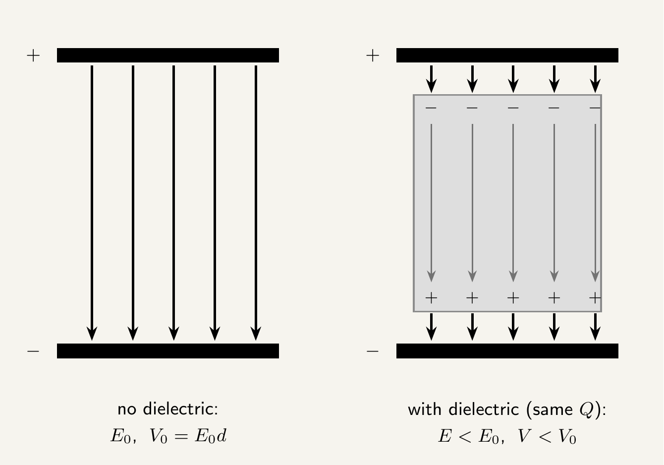
It's tempting to think the dielectric adds charge to the plates. It doesn't: $Q$ on the plates is set by whatever charged them and stays fixed. What changes is the electric field (and so the potential difference) produced by that charge, because the dielectric's own induced field partially cancels it. Lower $V$ for the same $Q$ is exactly what a larger capacitance means, since $C=Q/V$.
Relative permittivity
The extent to which a material increases capacitance is measured by its relative permittivity (also called the dielectric constant), $\varepsilon_r$ — the ratio of the capacitance with that material as the dielectric to the capacitance with a vacuum between the same plates:
Relative permittivity is a ratio of two capacitances, so it's dimensionless — just a number. For a vacuum, $\varepsilon_r=1$ exactly, by definition; air is so close to a vacuum that $\varepsilon_r\approx1$ for air too. Every real dielectric has $\varepsilon_r>1$, since inserting it can only increase capacitance, never decrease it. Typical values range from around 2–3 for waxed paper or many plastics up to several thousand for specialist ceramics used in compact high-capacitance components.
The parallel plate capacitor formula
Combining relative permittivity with the geometry of a parallel plate capacitor gives a formula for capacitance directly in terms of the capacitor's physical dimensions:
where $\varepsilon_0$ is the permittivity of free space ($8.85\times10^{-12}\,\text{F m}^{-1}$), $\varepsilon_r$ is the relative permittivity of the dielectric between the plates, $A$ is the area of overlap of the two plates, and $d$ is their separation. Each factor matches physical intuition: a larger plate area $A$ gives more room to store charge, so capacitance rises; a larger separation $d$ weakens the field for a given charge, so capacitance falls; and a dielectric with larger $\varepsilon_r$ suppresses the field more, boosting capacitance further still. With no dielectric (or air, $\varepsilon_r\approx1$), this reduces to $C=\varepsilon_0A/d$.
$C=Q/V$ is the universal definition of capacitance — it works for any capacitor, of any shape. $C=\varepsilon_0\varepsilon_r A/d$ is a specific consequence of that definition for the parallel-plate geometry, derived from the uniform field between two flat plates. Use $C=Q/V$ for charge/voltage questions on any capacitor; use $C=\varepsilon_0\varepsilon_r A/d$ only when a question gives you the physical dimensions of parallel plates.
Required Practical: Relative Permittivity and Capacitor Dimensions
This is part of AQA's specification content for parallel plate capacitors (topic 7.4.2), examined through practical skills in determining relative permittivity and investigating how capacitance depends on plate area and separation.
Equipment
| Equipment | Purpose |
|---|---|
| Parallel plate capacitor with adjustable separation | The component under investigation; allows $d$ to be varied directly |
| Set of dielectric sheets (known thickness, various materials) | Inserted between the plates to change $\varepsilon_r$ or vary $d$ precisely |
| Capacitance meter (or a charge/discharge circuit with known $R$) | Measures the capacitance of the plate arrangement |
| Vernier calipers or micrometer | Measures plate separation $d$ accurately |
| Metre ruler | Measures plate dimensions, to find overlap area $A$ |
Method
Sources of error and how to minimise them
The formula $C=\varepsilon_0\varepsilon_r A/d$ assumes a perfectly uniform field, which only holds away from the plates' edges — near the edges, field lines bulge outward ("fringing"), making the true capacitance slightly larger than the formula predicts. This effect is minimised by using plates whose separation $d$ is small compared with their overall dimensions.
Any small air gap left between a solid dielectric sheet and the plates acts as a second capacitor in series with much lower capacitance, significantly reducing the measured value below what the dielectric's true $\varepsilon_r$ would predict. Use dielectric sheets that fit snugly against both plates, and apply light, even pressure.
Reading $d$ with a ruler by eye introduces parallax error, particularly significant since $d$ is typically only a few millimetres. Use vernier calipers or a micrometer for precision, and take repeat readings at several points across the plates to check they remain parallel.
Key takeaways
- A dielectric is an insulator that increases a capacitor's capacitance when placed between its plates, by polarising and setting up a bound surface charge that partially cancels the plates' own field.
- Relative permittivity (dielectric constant) $\varepsilon_r=C_{\text{with dielectric}}/C_{\text{vacuum}}$ is dimensionless, equal to 1 for a vacuum, and greater than 1 for every real dielectric.
- For a parallel plate capacitor, $C=\dfrac{\varepsilon_0\varepsilon_r A}{d}$ — capacitance increases with plate area $A$ and relative permittivity $\varepsilon_r$, and decreases with plate separation $d$.
- $C=Q/V$ is the universal definition of capacitance; $C=\varepsilon_0\varepsilon_r A/d$ is the specific formula for parallel plates.
- Relative permittivity can be found experimentally by comparing capacitance with and without a dielectric, or from the gradient of a $C$ against $1/d$ graph; plotting $C$ against $A$ and against $1/d$ both give straight lines through the origin, verifying the formula.