Capacitance & Capacitor Networks
A capacitor is really just two conductors kept apart by an insulator, but that simple arrangement stores real, usable energy in the electric field between them. This lesson covers how much charge a capacitor holds for a given voltage, how much energy that represents, and what happens when you wire several together.
Capacitance
A capacitor stores electric charge by holding equal and opposite charges on two separated conductors — most simply, two parallel plates. The capacitance of a capacitor is defined as the charge stored per unit potential difference across it:
where $Q$ is the magnitude of charge stored on each plate and $V$ is the potential difference between them. Capacitance is measured in farads (F), where $1\,\text{F}=1\,\text{C V}^{-1}$. A farad is enormous for practical components — most capacitors are labelled in microfarads (μF), nanofarads (nF) or picofarads (pF). Larger capacitance means more charge stored for the same potential difference.
Energy stored in a capacitor
Charging a capacitor takes work: as charge builds up on the plates, each additional bit has to be pushed on against the repulsion of the charge already there, so potential difference rises as charging proceeds — unlike lifting a mass at constant height, where the force needed stays fixed.
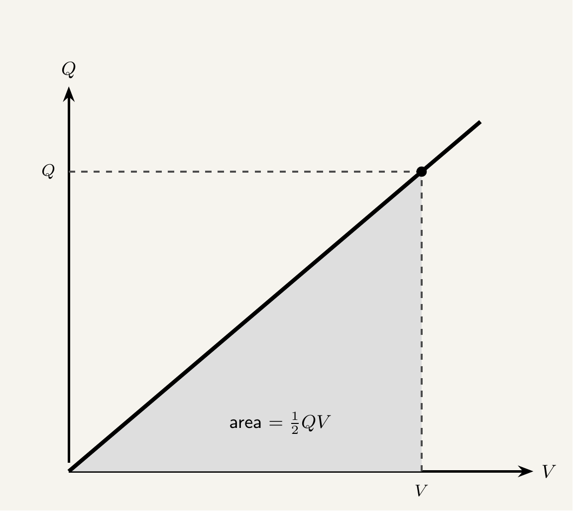
Using $C=Q/V$, this can be rewritten in two other equally useful forms:
All three are algebraically equivalent — pick whichever matches the quantities given.
Capacitors in series and parallel
Like resistors, capacitors combine into networks, but the rules turn out the opposite way round — a common source of exam errors.
Capacitors in parallel
Capacitors in parallel share the same potential difference across each (connected directly across the same two points), but each stores its own share of the total charge: $Q_{total}=Q_1+Q_2+\ldots$. Since $Q=CV$ with the same $V$ for each:
Connecting capacitors in parallel is equivalent to increasing the effective plate area, so the combined capacitance is larger than any individual one.
Capacitors in series
Capacitors in series all store the same charge $Q$ (charge pushed onto one plate induces an equal and opposite charge on the facing plate of the next, down the chain), but total potential difference is shared out: $V_{total}=V_1+V_2+\ldots$. Since $V=Q/C$ with the same $Q$ throughout:
For resistors, series adds directly ($R=R_1+R_2$) and parallel uses the reciprocal-sum rule. For capacitors it's reversed: parallel adds directly, series uses the reciprocal-sum rule. Resistance in series adds because the same current flows through a longer path; capacitance in series falls because the same charge is spread across effectively larger plate separation.
Two capacitors, $C_1=6.0\,\mu\text{F}$ and $C_2=3.0\,\mu\text{F}$, are connected first in parallel and then in series. Find the combined capacitance in each case.
Parallel: $C=6.0+3.0=9.0\,\mu\text{F}$.
Series: $\dfrac{1}{C}=\dfrac{1}{6.0}+\dfrac{1}{3.0}=\dfrac{1}{6.0}+\dfrac{2}{6.0}=\dfrac{3}{6.0} \implies C=2.0\,\mu\text{F}$.
Notice the series combination gives a smaller capacitance than either individual capacitor — the opposite of what happens with resistors in parallel, but exactly analogous to it mathematically.
Key takeaways
- Capacitance $C=Q/V$, measured in farads (F); most practical capacitors are μF, nF or pF.
- Energy stored in a charged capacitor: $E=\tfrac12QV=\tfrac12CV^2=\dfrac{Q^2}{2C}$, derived from the area under a Q–V graph (a triangle, giving the factor of a half).
- Capacitors in parallel add directly: $C=C_1+C_2+\ldots$ (same $V$, charges add).
- Capacitors in series combine reciprocally: $\dfrac{1}{C}=\dfrac{1}{C_1}+\dfrac{1}{C_2}+\ldots$ (same $Q$, voltages add).
- These rules are the reverse of the resistor combination rules — series capacitors behave like parallel resistors, and vice versa.