Series & Parallel Circuits
Two resistors can be wired together in only two fundamentally different ways — one after another, or side by side — and those arrangements behave completely differently. This lesson builds the maths behind both from first principles.
Two ways to connect a circuit
Take three resistors and a battery. There are only two sensible ways to wire them up. Chain them one after another so charge passes through the first, then the second, then the third, with no other route — a series connection. Or give each resistor its own branch between the same two points, so charge splits up and takes whichever path it likes — a parallel connection. Real circuits are usually a mixture of both, but you need to understand each piece separately first.
Each arrangement imposes a different constraint on current and voltage, and those constraints are what let us derive a formula for total resistance in each case.
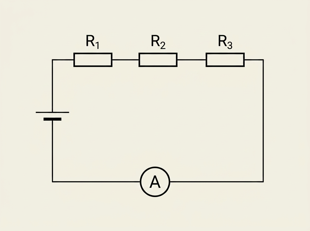
Resistors in series
Picture the three resistors wired in a single loop with the cell. Because there's only one path for charge, whatever current flows out of the cell flows through every resistor — there's nowhere else to go. So the current $I$ is the same everywhere in a series circuit.
The second fact comes from energy conservation: as a charge travels round the loop and back to where it started, all the energy it picked up from the cell must be used up along the way, shared among the resistors it passed through. So the total potential difference equals the sum of the individual potential differences.
This result is physical, not just mathematical: adding another resistor in series can only ever increase total resistance — more material for charge to fight through, no alternative route to relieve the pressure.
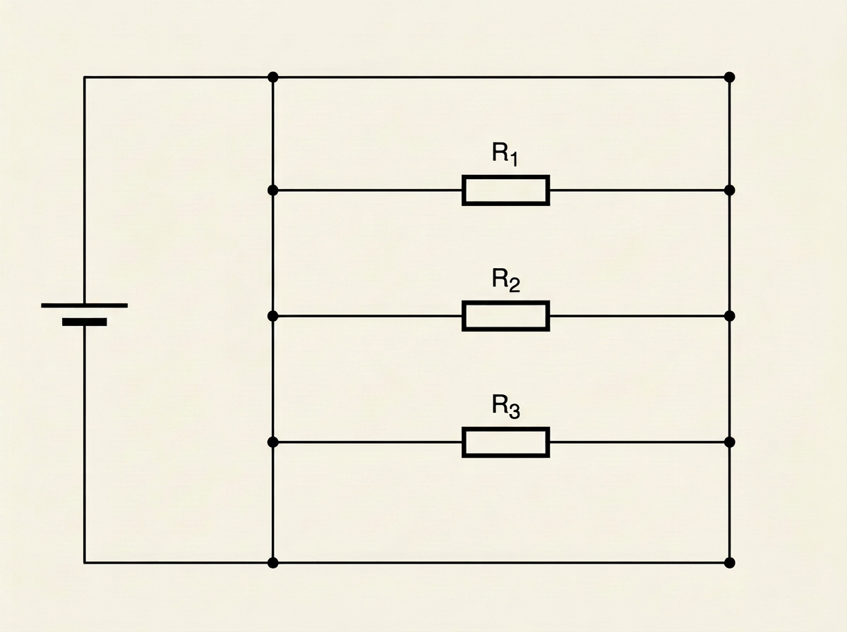
Resistors in parallel
Now spread the same three resistors into separate branches, each connected between the same two junction points. Because both ends of every resistor are tied to the same two points, each sees exactly the same potential difference. So the potential difference $V$ is the same across every branch.
The second fact is charge conservation at a junction: whatever current arrives has to leave again, so it splits among the branches on the way out and recombines to the same total on the way back. The total current supplied by the cell is the sum of the branch currents.
Notice the shape of the result is the mirror image of the series case — reciprocals instead of the resistances themselves. Physically, adding another parallel branch gives charge another route to escape by, so total resistance always goes down when you add a resistor in parallel, never up. This is why plugging more appliances into the same socket circuit increases the current drawn from the wall — each appliance is another parallel branch, lowering the overall resistance the supply sees.
Everything above comes down to two conservation laws that hold in any dc circuit. Conservation of charge means current into any junction equals current out, and current is the same at every point around a loop with no junctions. Conservation of energy means that, round any complete loop, the total energy supplied per unit charge (sum of the emfs) equals the total energy transferred per unit charge (sum of the potential drops). Series and parallel formulas are just these two laws worked through for two particular arrangements.
These have their own names: Kirchhoff's first law is the charge-conservation statement — current in equals current out at a junction — and Kirchhoff's second law is the energy-conservation statement around a closed loop.
Power in a circuit
Current tells you how much charge flows per second; potential difference tells you how much energy each coulomb transfers as it passes through a component. Multiply them and you get energy transferred per second — power. Over a time $t$, total energy transferred is $E = IVt$, and the rate of transfer is $P = IV$.
Because $V$, $I$ and $R$ are linked by $V=IR$ for a resistor, the power equation can be rewritten in two other useful forms.
Cells in series and parallel
The same series/parallel thinking applies to cells, not just resistors. Connect identical cells in series, positive terminal to negative terminal, and their emfs add — two 1.5 V cells in series drive a circuit with a combined emf of 3 V, since each charge passing through picks up energy from both cells in turn.
Connect identical cells in parallel instead, and the combined emf stays the same as a single cell, but the arrangement can now supply more current, or supply the same current for longer, since the total charge delivered is shared between the cells rather than coming from one. This is the parallel-branch idea from earlier, applied to sources of emf instead of resistors.
Key takeaways
- In series, resistors share the same current, and their potential differences add — giving $R_{total} = R_1 + R_2 + R_3 + \ldots$, which always increases as you add resistors.
- In parallel, resistors share the same potential difference, and their currents add — giving $\dfrac{1}{R_{total}} = \dfrac{1}{R_1} + \dfrac{1}{R_2} + \dfrac{1}{R_3} + \ldots$, which always decreases as you add resistors.
- Both derivations rest on the same two ideas: conservation of charge (current in equals current out at a junction) and conservation of energy (potential difference measures energy transferred per unit charge) — also known as Kirchhoff's first and second laws respectively.
- Power delivered to a resistor can be written as $P=IV$, $P=I^2R$ or $P=V^2/R$ — three forms of the same relationship, related by substituting $V=IR$ or $I=V/R$.
- Energy transferred over a time $t$ is $E = IVt$ — power is just this rate of energy transfer.
- Identical cells in series add their emfs together; identical cells in parallel keep the same combined emf but can supply more current, or supply it for longer.