Potential Dividers
Take one supply voltage and split it into any fraction you like, just by choosing two resistors — that's the whole idea behind a potential divider. This one circuit is the backbone of almost every sensor you'll meet in electronics, from thermostats to light-sensing streetlamps.
Splitting a voltage on purpose
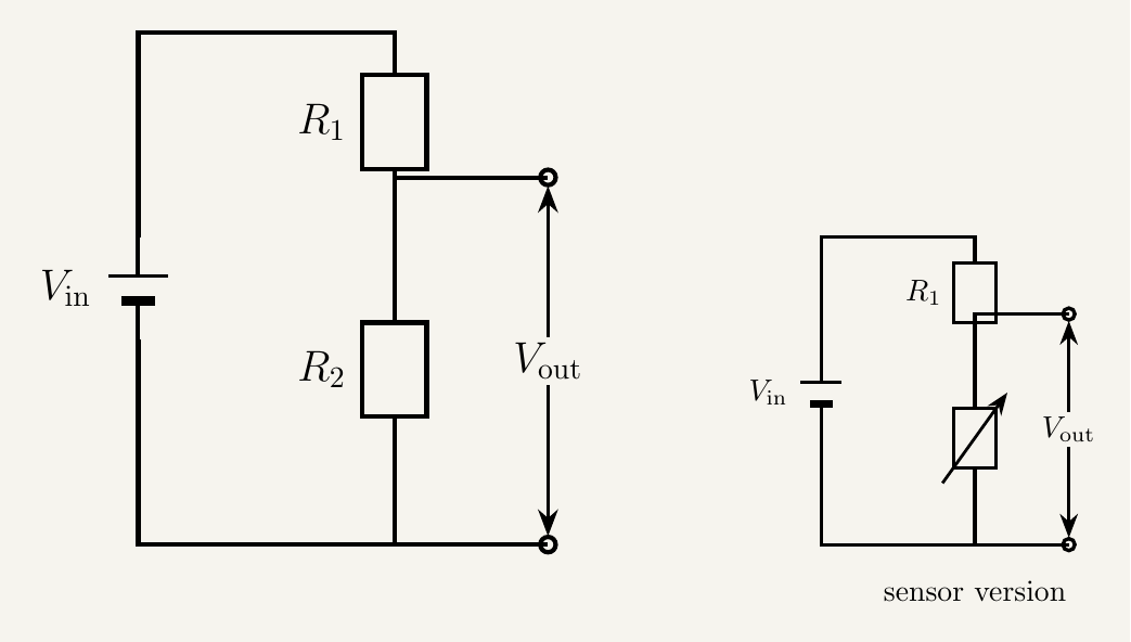
Suppose you've got a 6 V supply, but the sensor you want to power only needs 2 V. You could find a battery supplying exactly 2 V — or take the 6 V you already have and divide it down using two resistors in series. That's the entire job of a potential divider: two resistors connected in series across a supply, with an output voltage taken from the point where they meet.
The junction between the two resistors sits at some voltage between the top of the chain and the bottom, depending on how the two resistances compare. Make the bottom resistor much bigger than the top one and most of the supply voltage appears across it, so the output is close to the full supply voltage. Make it much smaller and the output is close to zero — anywhere in between, you can dial in whatever fraction you want.
Deriving the potential divider formula
Because R1 and R2 are wired in series, the same current flows through both. That single fact is enough to derive the ratio formula, with careful bookkeeping using $V = IR$.
Read the formula the way it's built rather than memorising it blind: the output voltage is the input voltage multiplied by "the fraction of the total resistance that belongs to the resistor you're measuring across." Swap the output to be taken across R1 instead, and you simply swap which resistance sits on top of the fraction.
Turning a divider into a sensor
A potential divider made from two fixed resistors is only mildly interesting — the output voltage is fixed too, set once the resistors are chosen. Replace one resistor with a component whose resistance changes in response to the outside world, though, and the output voltage starts responding to that world too. This is where potential dividers become genuinely powerful.
- Swap in a thermistor — resistance changes strongly with temperature — and the output voltage becomes a direct electrical signal for temperature.
- Swap in a light-dependent resistor (LDR) — resistance falls as light intensity rises — and the output voltage becomes a signal for brightness.
- Swap in a variable resistor (potentiometer) and you get a manually adjustable output — a volume control is really just a potential divider with a knob.
This is enormously useful in practice, since most of the physical world doesn't naturally come as a voltage — temperature, brightness, position, pressure. A potential divider built around the right sensing component lets electronic circuitry "read" one of these quantities, by converting it into an output voltage a measuring or control circuit can process directly.
It's worth reasoning through the direction $V_{out}$ moves, not just recognising that it changes, since exam questions test this directly. Suppose the thermistor is in the $R_2$ position. If temperature rises, the thermistor's resistance falls (its NTC behaviour), so $R_2$ falls, the fraction $R_2/(R_1+R_2)$ shrinks, and $V_{out}$ falls too — a rising temperature produces a falling output voltage. If the thermistor were in the $R_1$ position instead, the same temperature rise would shrink $R_1$, shrinking the denominator while $R_2$ stays fixed, so the fraction — and $V_{out}$ — would rise instead. Swapping which arm holds the sensor flips the sign of the response, even though the sensor itself behaves identically.
The same reasoning carries across to an LDR. With the LDR as $R_2$, rising light intensity lowers $R_2$, so $V_{out}$ falls — a brighter room gives a smaller output voltage. Swap the LDR into the $R_1$ position, and rising light intensity now raises $V_{out}$ instead, for the same reason as the thermistor case.
A potential divider doesn't have to give a fixed output. Two fixed resistors give a fixed fraction of the supply voltage — useful for scaling a voltage down by a set amount. Replace both arms with a single variable resistor (a potentiometer with a sliding contact), and the same idea gives a continuously adjustable output, smoothly variable between zero and the full supply voltage as the slider moves.
Key takeaways
- A potential divider is two resistors in series across a supply voltage, with the output taken from the junction between them.
- The formula $V_{out} = V_{in}\times\dfrac{R_2}{R_1+R_2}$ follows directly from the series-circuit fact that both resistors share the same current — divide $V=IR_2$ by $V=I(R_1+R_2)$ and the current cancels.
- The output is Vin scaled by the fraction of the total resistance that belongs to the resistor you're measuring across.
- Replacing one fixed resistor with a thermistor, LDR, or other resistance-varying component turns a potential divider into a sensor circuit, with an output voltage that tracks a physical quantity like temperature or light intensity.
- The direction $V_{out}$ moves depends on which arm holds the sensor: a thermistor or LDR as $R_2$ gives a falling output as temperature or light rises, but the same component as $R_1$ gives a rising output for the same change — work it through via the $R_2/(R_1+R_2)$ fraction rather than memorising it.
- This makes potential dividers the standard way of interfacing real-world physical conditions with electronic measurement or control systems.
- Two fixed resistors give a fixed output fraction; a variable resistor used across the whole divider gives a continuously adjustable output voltage instead.