E.m.f. & Internal Resistance
Ever wondered why a battery reading "9 V" on the label never quite delivers 9 V once wired into a circuit? The gap between what a cell promises and what it delivers comes down to one idea: no real cell is a perfect source of energy, and this lesson is about the resistance hiding inside it.
What emf actually means
Every cell or battery is, at heart, an energy converter — chemical energy goes in, electrical energy comes out, one coulomb of charge at a time. The electromotive force, or emf, of a source is the energy it supplies per unit charge: $\varepsilon = \dfrac{E}{Q}$, measured in volts, exactly like potential difference.
That similarity in units trips students up, because emf and potential difference describe two different things, not the same thing wearing two names. Emf describes energy being supplied — it's the property of a source, like a cell, converting one form of energy into electrical energy. Potential difference describes energy being transferred elsewhere — it's the property of a component, like a resistor, converting electrical energy into some other form, typically heat.
Why no real cell is perfect
If a cell were a perfect source of energy, every joule of chemical energy it converted would show up at its terminals ready for useful work. But cells are made of real materials — electrolytes, electrodes — none of them perfect conductors. So charge has to do some work fighting its way through the inside of the cell itself before it even reaches the external circuit.
This unavoidable internal resistance, symbol $r$, means that whenever current flows, some of the energy supplied by the cell is used up inside the cell itself, transferred as heat within its own materials, and never makes it to the external circuit at all.
Deriving ε = I(R + r)
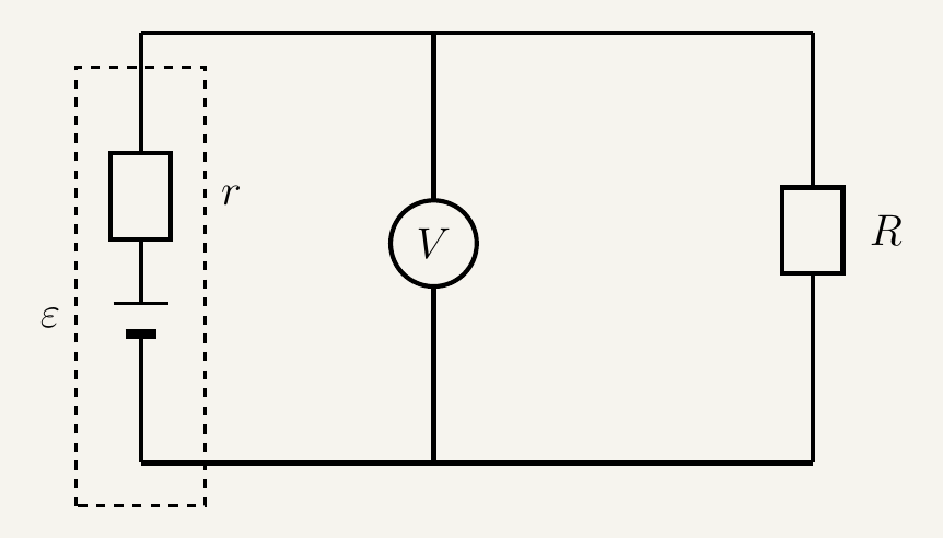
Picture the cell as a perfect source of emf $\varepsilon$ in series with a small internal resistance $r$, connected to an external resistor $R$. The relationship between them falls straight out of energy conservation — energy can't simply vanish as charge moves around the loop.
This equation is why a battery never quite delivers its full rated voltage once current is flowing — some emf is always "spent" internally, growing with the current drawn.
Terminal pd, and where it comes from
The voltage you'd measure across a cell's terminals with a voltmeter — the terminal pd, $V$ — is what's left of the emf once the share lost to internal resistance is subtracted. Rearranging the equation above makes this explicit.
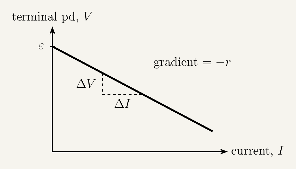
That intercept has a nice physical meaning: it's the terminal pd you'd read with almost no current flowing at all, when there's essentially nothing left to lose internally. As soon as real current flows, terminal pd drops below the emf, more steeply the larger the internal resistance.
The graph's other axis crossing is worth attention too. Setting $R=0$ in $\varepsilon = I(R+r)$ — a short circuit, where external resistance has effectively vanished — gives $\varepsilon = Ir$, so the short-circuit current is $I = \varepsilon/r$. On the graph, this is the $x$-intercept: the current at which $V=0$, meaning all the emf is lost driving current through the internal resistance alone. Because $r$ is normally very small, $I = \varepsilon/r$ can be very large — why short-circuiting a battery is dangerous: even a modest emf divided by a small internal resistance gives enough current to dump a lot of power ($I^2r$) inside the cell, heating it rapidly and, in the worst cases, damaging it.
Required Practical: Investigating EMF and Internal Resistance
This is AQA's Required Practical 6: measuring a cell's emf and internal resistance.
Equipment
| Equipment | Purpose |
|---|---|
| Cell or battery under test | The source whose emf and internal resistance are being found |
| Variable resistor (rheostat) | Varies the current drawn from the cell |
| Ammeter | Measures the current $I$ |
| Voltmeter | Measures the terminal pd $V$ across the cell |
| Switch | Opens the circuit between readings, limiting unnecessary discharge/heating |
| Connecting leads | Completes the circuit |
Method
Sources of error and how to minimise them
Leaving the circuit connected for too long lets the cell warm up, changing its internal resistance between readings. Take readings reasonably quickly, and open the switch between them where practical.
An ammeter with significant resistance, or a voltmeter that draws a non-negligible current, both slightly distort the readings. Use an ammeter with as low a resistance as possible and a voltmeter with as high a resistance as possible, so both stay close to the ideal assumption used in the derivation.
Poor connections add extra resistance that isn't part of the cell's own internal resistance. Check and secure all connections, and clean contacts if readings look inconsistent.
Combining cells: series and parallel
Real circuits rarely rely on a single cell. Torches, remote controls and battery packs combine several identical cells for either a bigger voltage or more current capability — and both the combined emf and internal resistance follow directly from the same reasoning above, applied to more than one cell at a time.
Cells in series
When cells are connected in series — positive terminal to negative terminal, around a single loop — exactly the same current $I$ flows through every cell in turn, because there's only one path for charge.
This only holds if every cell is connected the same way round. If one cell is reversed relative to the others, its emf subtracts from the total instead of adding — a cell inserted backwards into a torch fights against the rest of the pack, which is why the total emf of two identical opposing cells in series is zero, not double.
Identical cells in parallel
Connecting cells in parallel instead — all positive terminals joined to one node, all negative terminals to another — changes the picture. Every cell shares the same pair of terminals, so every cell must have the same terminal pd, but the current can now split between them.
So $n$ identical cells in parallel behave as a single source with the same emf as one cell, but with internal resistance shared out $n$ ways, exactly as ordinary resistors combine in parallel. That's the point of wiring cells in parallel: it doesn't raise the available voltage, but it lowers the effective internal resistance, so the combination can supply more current before its terminal pd sags noticeably. Series combinations do the opposite — they raise the available emf, at the cost of adding the internal resistances too.
Key takeaways
- Emf, $\varepsilon = E/Q$, is the energy supplied per unit charge by a source — it describes energy being supplied, not transferred elsewhere.
- Potential difference describes energy being transferred or converted by a component; emf and pd are measured in the same unit but describe different roles in a circuit.
- Internal resistance $r$ is an unavoidable property of any real cell, causing some energy to be transferred inside the cell itself whenever current flows.
- Energy conservation around the loop gives $\varepsilon = I(R+r)$, splitting the emf into a share delivered externally ($IR$) and a share lost internally ($Ir$).
- Rearranged, $V = \varepsilon - Ir$ shows the terminal pd falls as current increases, at a rate set by the internal resistance.
- A graph of terminal pd against current is a straight line with y-intercept $\varepsilon$ and gradient $-r$ — this is exactly how emf and internal resistance are found experimentally.
- Setting $R=0$ (a short circuit) gives $\varepsilon = Ir$, so the short-circuit current is $I=\varepsilon/r$ — the graph's $x$-intercept — and because $r$ is usually tiny, this current can be dangerously large.
- Cells in series: emfs add ($\varepsilon_{\text{total}} = \varepsilon_1+\varepsilon_2+\dots$) and internal resistances add ($r_{\text{total}} = r_1+r_2+\dots$) — but a reversed cell subtracts its emf instead.
- $n$ identical cells in parallel keep the same emf $\varepsilon$ as a single cell, but the combined internal resistance drops to $r/n$, letting the combination supply more current with less terminal-pd sag.