Physics · Magnetic Fields · A2 Level

Transformers

A transformer uses electromagnetic induction to step an alternating voltage up or down, with no moving parts. This lesson derives the turns-ratio equation, looks at why the National Grid relies on transformers to keep transmission losses down, and covers the main sources of energy loss in a real transformer.

8 min read

How a transformer works

A transformer consists of two coils — the primary (with $N_p$ turns) and the secondary (with $N_s$ turns) — wound around a shared, soft-iron core. An alternating voltage $V_p$ applied to the primary drives an alternating current, which sets up an alternating flux in the iron core. The core channels almost all of that flux through the secondary coil as well, so the same changing flux links both coils and induces an alternating emf, $V_s$, in the secondary.
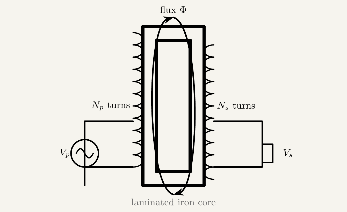
A schematic diagram of a transformer, showing a rectangular laminated iron core with a primary coil of Np turns wound on the left and a secondary coil of Ns turns wound on the right. An AC voltage source Vp is connected to the primary coil, and a load Vs is connected to the secondary coil. Arrows around the core show the magnetic flux linking the two coils.
The primary coil's alternating current sets up an alternating flux in the shared iron core, which links the secondary coil and induces an alternating emf there.

Because it's the same core flux inducing an emf in both coils, and because emf per turn is set entirely by the rate of change of that shared flux, the two voltages scale directly with the number of turns:

DerivationTurns-ratio equation, Vs/Vp = Ns/Np
1
Emf induced per coil follows Faraday's law: $V_p=N_p\dfrac{d\Phi}{dt}$ and $V_s=N_s\dfrac{d\Phi}{dt}$.
Both coils link the same flux $\Phi$ at every instant, since (ideally) none of the flux escapes the core.
2
Divide the two equations: $\dfrac{V_s}{V_p} = \dfrac{N_s\,d\Phi/dt}{N_p\,d\Phi/dt}$.
3
The $d\Phi/dt$ terms cancel: $\displaystyle \frac{V_s}{V_p} = \frac{N_s}{N_p}$.
▪ derived

A step-up transformer has $N_s>N_p$ and increases the voltage; a step-down transformer has $N_s

Power conservation and the current relationship

An ideal transformer has no energy losses, so the power delivered to the primary equals the power delivered by the secondary: $I_pV_p=I_sV_s$. Combining this with the turns-ratio equation gives the corresponding relationship for current:

$\dfrac{I_s}{I_p} = \dfrac{N_p}{N_s} = \dfrac{V_p}{V_s}$

Notice this is the inverse of the voltage ratio — a step-up transformer that raises voltage necessarily lowers current in the same proportion, and vice versa. A transformer can change voltage and current, but never the power (in the ideal case).

Why the National Grid uses transformers

Minimising transmission losses

Power lost to resistive heating in a transmission cable is $P_{\text{loss}}=I^2R$, which depends on the square of the current — not on the power being transmitted. Stepping the voltage up before transmission (using a step-up transformer at the power station) reduces the current needed to deliver the same power, $P=IV$, and cuts resistive losses dramatically. The National Grid transmits at very high voltages (hundreds of kV) for exactly this reason, then uses step-down transformers to bring the voltage back down to safe, usable levels before it reaches homes and businesses.

Real transformers: efficiency and losses

Real transformers aren't perfectly efficient — some input power is always lost as heat rather than delivered to the secondary. Efficiency is defined as:

$\eta = \dfrac{\text{output power}}{\text{input power}} = \dfrac{I_sV_s}{I_pV_p} \times 100\%$

Well-designed transformers can reach efficiencies above 99%, but the main sources of loss are:

  • Resistive (copper) losses — the coils have some resistance, so current flowing through them dissipates power as $I^2R$ heating, just like in any wire.
  • Eddy current losses — the changing flux also induces circulating currents directly within the iron core itself, which dissipate energy as heat. Laminating the core — building it from thin, electrically insulated sheets rather than one solid block — breaks up these current loops and greatly reduces this loss.
  • Hysteresis losses — repeatedly magnetising and demagnetising the core as the flux alternates costs energy, dissipated as heat, due to the core material's magnetic hysteresis.

Key takeaways

  • A transformer links a primary and secondary coil through a shared alternating flux in an iron core, inducing an emf in the secondary via electromagnetic induction.
  • Turns-ratio equation: $\dfrac{V_s}{V_p}=\dfrac{N_s}{N_p}$ — step-up ($N_s>N_p$) increases voltage, step-down ($N_s
  • For an ideal (lossless) transformer, power is conserved: $I_pV_p=I_sV_s$, giving $\dfrac{I_s}{I_p}=\dfrac{N_p}{N_s}$ — current and voltage scale inversely.
  • Since resistive transmission loss $P_{\text{loss}}=I^2R$ depends on current, the National Grid transmits at high voltage (and correspondingly low current) to minimise losses, then steps down for safe use.
  • Real transformers lose some power as heat, mainly through resistive (copper) losses in the coils, eddy currents in the core, and hysteresis in the core material; lamination of the core reduces eddy current losses.