I–V Characteristics
If resistance is a single number, an I–V characteristic is the full story: a graph showing exactly how a component's current and voltage relate across its whole operating range. Three shapes come up again and again in this course, and each is a direct signature of the physics inside the component.
What an I–V characteristic actually shows
An I–V, or current-voltage, characteristic is a graph of current through a component plotted against potential difference across it, built up from a series of readings as the applied voltage is varied. Rather than quoting a single resistance value at one operating point, the graph shows how that ratio changes — or doesn't — across the component's whole range of behaviour.
You'll see this presented both ways round: current on the vertical axis and voltage on the horizontal, or vice versa, depending on which quantity a given experiment controlled. Neither is more "correct" — what matters is that the gradient (or its reciprocal) still tells you about resistance regardless of which axis is which.
Ohmic conductor: a straight line through the origin
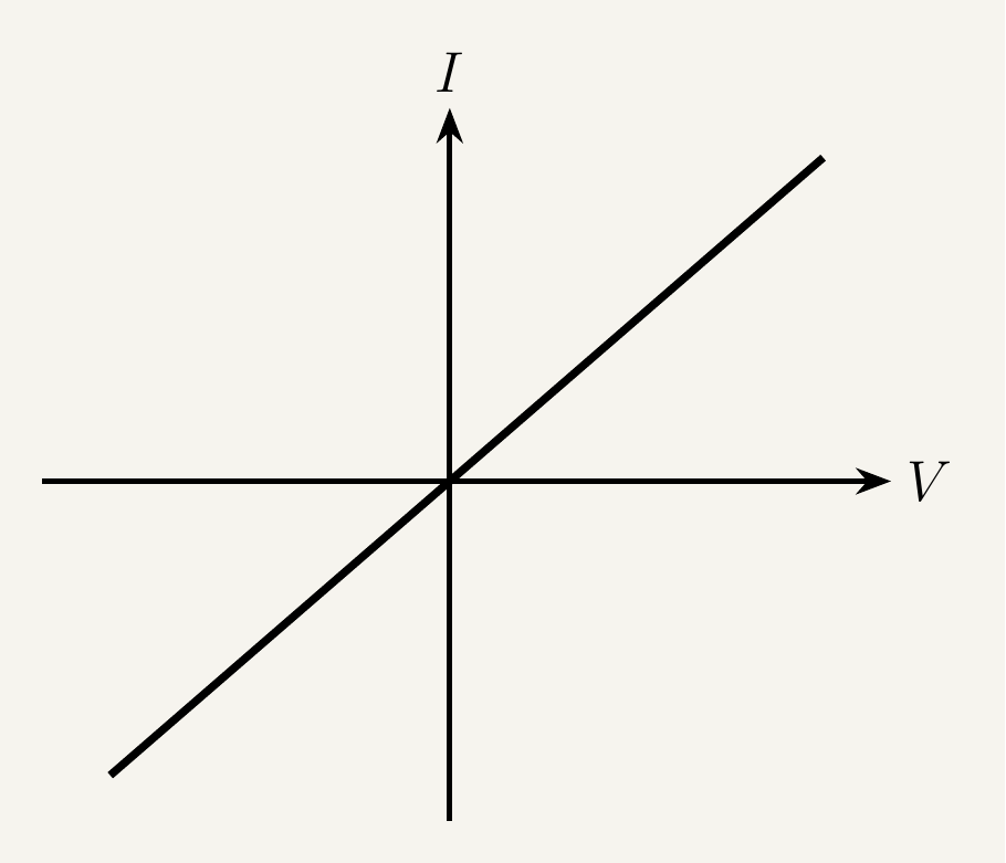
For a conductor obeying Ohm's law — held at constant temperature — the I–V characteristic is the simplest shape possible: a straight line through the origin. Because $I \propto V$, doubling the voltage doubles the current at every point. The gradient, $\Delta I/\Delta V$, is constant everywhere and equal to $1/R$ — a steeper line means lower resistance, a shallower one means higher. The straight line is a direct graphical statement that resistance isn't changing anywhere along it.
Filament lamp: a curve that flattens out
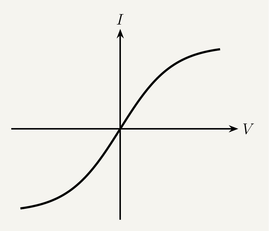
A filament lamp's I–V characteristic starts steep near the origin, then curves over and flattens as current increases. It's worth understanding where this comes from physically rather than just memorising the shape.
At low current, the filament is relatively cool, its ions aren't vibrating vigorously, and drifting electrons pass through with few collisions — so resistance is low and the graph is steep, close to an ohmic conductor's shape. As current increases, the filament heats up substantially (the whole point of a lamp is to get hot enough to glow). As temperature rises, lattice ions vibrate more, presenting a bigger obstacle to drifting electrons — more collisions mean higher resistance. So as $V$ increases, resistance climbs, and each further increase in voltage buys a progressively smaller increase in current — graphically, a curve that starts steep and bends over.
Because a filament lamp's resistance depends on its own operating temperature — which depends on the current flowing through it — it's a textbook example of a non-ohmic component, even though it's just a piece of resistance wire.
Diode: almost nothing, then a threshold, then a steep rise
A semiconductor diode's I–V characteristic looks nothing like the previous two, because a diode is built to behave differently depending on which way round it's connected.
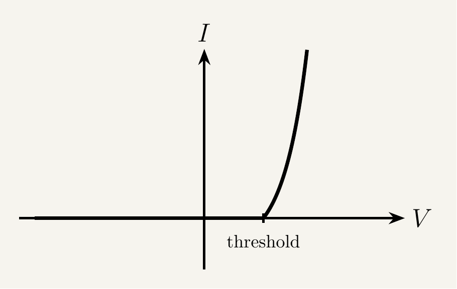
In forward bias, almost no current flows until the voltage reaches a threshold, the turn-on voltage — around 0.6–0.7 V for silicon — beyond which current rises steeply. In reverse bias, current stays negligibly small across a wide range of voltages, up until a much larger "breakdown" voltage, beyond which the diode can be damaged.
The physical reason lies at the junction between the diode's two halves, where a narrow depletion region forms, swept clear of free charge carriers, acting as a barrier. In reverse bias, the applied voltage reinforces that barrier and virtually no carriers have enough energy to cross it. In forward bias, the applied voltage lowers the barrier — but only once it exceeds the threshold does the barrier become low enough for significant numbers of carriers to cross. Beyond that point, carriers pour across for each small voltage increase, giving the sharp upward bend on the graph.
When asked to explain an I–V characteristic in an exam, the mark scheme almost never wants "the line curves over" on its own. It wants the physical mechanism: what's changing inside the component (temperature, charge carrier availability, a barrier being overcome) that changes the resistance.
Key takeaways
- An I–V characteristic plots current against potential difference across a component's full operating range, summarising its behaviour in one graph; either quantity may be on the horizontal axis.
- An ohmic conductor at constant temperature gives a straight line through the origin, with constant gradient $1/R$.
- A filament lamp's characteristic starts steep and flattens as current increases, because rising temperature increases lattice vibration, which increases electron-ion collisions and therefore resistance.
- A diode carries negligible current in reverse bias (up to breakdown) and negligible current in forward bias until a threshold "turn-on" voltage (about 0.6–0.7 V for silicon), beyond which current rises steeply.
- The diode's threshold behaviour comes from the depletion region at its junction acting as a barrier that charge carriers can only cross once forward bias exceeds a critical value.
- In every case, the shape of the curve is a direct graphical signature of a physical mechanism changing the component's resistance — not an arbitrary pattern to memorise.